Pool pump maintenance and troubleshooting are always of high interest to customers. We receive a wide range of emails and calls about various test equipment to troubleshoot pool motors. For service technicians and installers, having the proper test equipment and understanding how to use these tools is essential.Last September, Century Pool Motors released an e-newsletter discussing the various tools needed to properly test pool pump motors. In the article, they discuss these tools and also provide basic instructions on how to properly use them.
Conventional Ohmmeter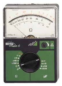
An ohmmeter is an electrical instrument used to measure the electrical resistance of motor windings. The ohmmeter will have various ranges from R x 1, where the meter reads directly in Ohms, to R x 100, where the meter reading must be multiplied by 100 for the actual ohm value.
This equation, derived from Ohm’s law, measures the value of the resistance ( R) R = Voltage/ Constant Current
Before Using An Ohmmeter
- Make sure the power is off.
- Read the instruction manual for the meter before operating.
- All troubleshooting checks specify the ohmmeter range that should be used. If your meter does not have this exact range, use the next higher range.
Digital Ohmmeter /Multimeter 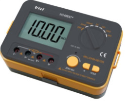
Digital ohmmeters are available and are heavily used in today’s field. A digital ohmmeter is one whose readout is digital – in the form of numbers as opposed to analog. If you are using a digital one, you do not need to set the ohmmeter range. The ohmmeter will display the value up to the maximum capability of the ohmmeter. Simply install the probes and take the resistance reading as normal.
We offer a brief tutorial on how to use a multimeter for your pump motor under How To Guides on our website. You can access the guide by clicking this link.
Ammeter
An ammeter is a measuring instrument used to measure the electric current in a circuit. (Electric currents are measured in amperes, hence the name). A pool owner would use an ammeter to measure the flow of currents to ensure correct wiring flow. In short, an ammeter is just a “flow meter” thats intended to measure current flow to the motor.
Take the motor leads and install them to the bottom of the ammeter. Then, select the desired voltage scale. You can take the readings by touching one probe to each of the lead line terminals.
Voltmeter
A voltmeter is used for measuring the electrical potential difference between two points in an electric circuit. It checks for AC or DC voltages, resistance, and continuity of electrical components. It allows you to check to see if there is a voltage present on a circuit.
To operate the voltmeter, arrange the leads so that the “jaws” will encircle one of the leads. Set the meter on maximum amp scale and encircle jaws around one lead and take a reading. It may be necessary to reset to a lower scale.
Checking the Voltage
- Ensure power is OFF
- Determine motor voltage (the motor label will indicate) and set meter accordingly.
- Reconnect power
- Start the motor
** CAUTION: All wires are live (hot), use extreme care!
The voltage reading should be within 10% of the motor nameplate voltage i.e, between 207 and 253 volts for a 230 V motor. If no voltage is recorded, check the fuses, circuit breakers, timers, and wiring for open connections or broken wires. If the voltage is not within the 10%, contact the proper utility company.
Make sure to check out our handy Step by Step Guide on How to Test your Pool Pump Voltage
Checking the Amperage
- Ensure power is OFF
- Set scale based upon the maximum load amps
- Position one lead (L1 or L2) so that the jaws can encircle one power lead. It’s usually necessary to install a test loop to have room for the meter jaws.
- Ensure the motor switch and governor are free of obstructions.
- Reconnect power and start the motor.
- Take your reading. The value should not exceed the maximum load amps (service factor amps) listed on the motor label.
** CAUTION: All wires are live (hot), use extreme care!
Ground Check
Readings for the ground may vary from day to day depending on the humidity levels. The ground fault device is seeing a total leakage of all loads on the circuit. All readings of less than 10K could indicate a ground. New motors typically read over one megaohm, while old motors with dust, dirt, and moisture could show a resistance to the ground below 10K and still run satisfactorily.
Checking the Ground
- Ensure the power is OFF
- Set device to R x 1K
- Attach one probe to the ground screw on the end frame and touch the other probe to all terminals on the terminal board, switch, capacitor, and protector.
- If grounded, check all external lead for cuts, breaks, frayed wires, etc.
- If ground is in the stator, the motor must be replaced
Checking the Start Switch
- Ensure the power is OFF
- Remove the canopy
- Discharge the capacitor by touching the two terminals simultaneously with the blade of an insulated handle screwdriver.
- Make sure there are no obstructions preventing the proper operation of the rotating governor. Also, check the governor to ensure the flipper moves freely
- You may want to check the contacts for severely burned or pitted contacts, switching etc. Some blackening is normal once the motor has been in use
- Replace the switch if there is any doubt. – DO NOT try to repair the switch by bending the contact blades!
If you determine that your Start Switch needs to be replaced then check out our handy Step by Step Guide on How to Replace your Pool Motor Start Switch
Protector (Thermal Overload)
- Set ohmmeter to R x 1
- The resistance between terminals 1 and 2 should be approximately 0. The resistance between 2 and 3 should be approx. 0.
- If it exceeds 1 ohm, you should replace it.
*TIP* Motorcycling on overload indicates some other problem, not just a defective overload.
If you determine that your Thermal Overload Protector needs to be replaced then check out our handy Step by Step Guide on How to Replace a Pool Motor Thermal Overload Protector
Capacitor Check (Start or Run)
- Set ohmmeter to R x 1
- Slip a heavy piece of paper or construction paper between points on the switch.
- Discharge the capacitor by touching the two terminals simultaneously with the blade of an insulated handle screwdriver.
- Attach one probe to each terminal (The ohmmeter needle should move rapidly to right then slowly drift to left)
- Replace capacitor if found to be bad
*TIP* The replacement capacitor must be the same MFD as the original. If the same exact voltage is not available, you can use the higher voltage.
If you determine that your Capacitor needs to be replaced then check out our handy step by step guide on How to Replace a Pool Motor Capacitor




My motor hummed & was told it was a bad capacitor. I replaced it & was quite relieved that it started to work again. Several hours later, when it was time to run the pump/motor again through a timer; It hummed once again & didn’t run the motor. I was back in square 1. Any recommendations?
Thanks in advance!
Test your motor’s circuit voltage. If the motor is repeatedly blowing capacitors, you may have a voltage issue. I’d also check the flow of the pump to see if you can get it running again. If the flow is low or priming issues arise, your motor may be running “lightly loaded,” leading to capacitor damaging voltage spikes.
Thank you for your advise Matthew. Add’l info: I can spin the shaft with 2 fingers & seems to turn without resistance. Also, the motor is able to run the following morning with no issues but it could never run again the same day. Any thoughts? Lastly, what do you mean by lightly loaded? Thanks again
I don’t know why it would run the next day’s schedule but not the same day; unless it’s overheating or the schedule/timer is not set up correctly. But as I said, you need to start by taking a meter to the motor. Spinning the shaft and sounds can only tell you what it could be; it doesn’t always tell you what it is.
Helpful articles: How to Test a Pool Pump Capacitor – How To Use a Multimeter to Test a Pool Pump Motor – Winding Resistance
Thanks, Charlie. One thing…you wrote “Replace capacitor if found to be bad” but could you connect the dots for me. Is it considered to be bad if, what–the ohmmeter needle doesn’t quickly move to the right and then slowly go to the left?
Thanks!
If it doesn’t follow that pattern of movement it would be considered a faulty capacitor.
Nice explanation